Introduction
Modern automatic transmissions aren’t just hydraulics anymore. They’re smart. Controlled by electronics. Tuned to the engine. And at the heart of that complexity sits the Variable Line Pressure (VLP) system. Textbooks talk about line pressure as a static measure — but in today’s vehicles, it moves. Adjusts. Responds. In real time. And that means when something goes wrong, the signs are subtle unless you know where to look. In this article, you’ll learn which live-data parameters really matter for monitoring VLP, how those signals reveal what’s happening inside, and how you as a technician or enthusiast can use them to diagnose problems with clarity rather than guesswork.
Understanding Variable Line Pressure (VLP)
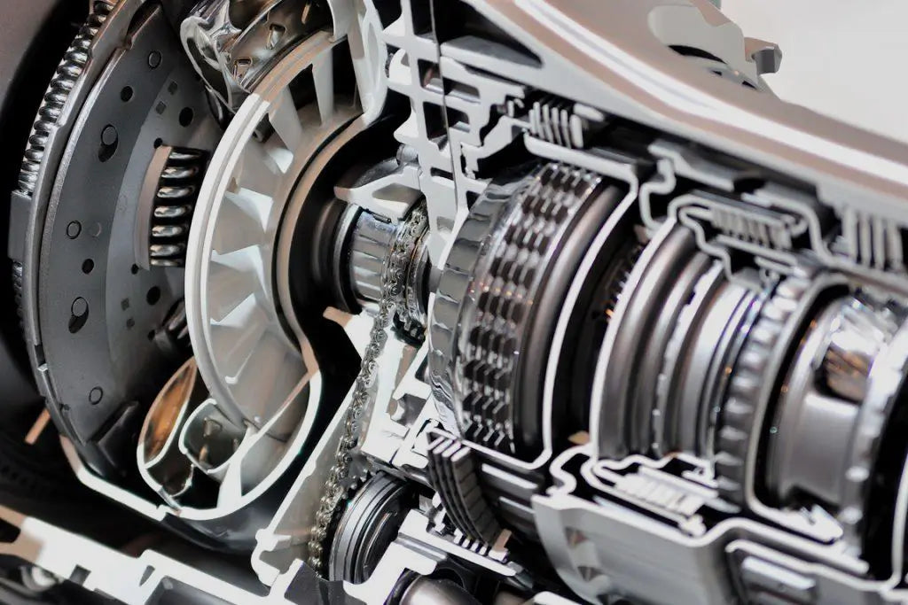
At its core, VLP is a system designed to dynamically adjust hydraulic pressure inside an automatic transmission. The goal is simple: deliver just enough pressure to engage the required clutches for the current driving condition — not too much, not too little. Traditional transmissions operated at a fixed line pressure. That meant more wear or more slip. VLP resolves this by allowing the Transmission Control Module (TCM) to modulate pressure based on real-time load, throttle input, vehicle speed, and fluid temperature.
What does this look like in practice? When you floor the throttle from 30 to 60 mph, the engine torque leaps. The car demands force. The TCM says, “Raise line pressure now.” The hydraulic pump whirs. The solenoid opens. Pressure builds. Clutches clamp. Shift engages. Later, when you’re coasting, the TCM reduces pressure. Less stress. Better efficiency. That loop — command, reaction, feedback — is what live data helps you verify.
Why Monitoring VLP and Transmission Live Data Matters
Fault codes tell you what failed. Live data tells you why it failed and how it’s behaving now. That’s a big difference. By monitoring live parameters you can:
-
Detect underlying issues before a fault code lights up.
-
Confirm whether a repair restored correct function — not just cleared a code.
-
Watch clutch adaptation over time and assess future wear.
-
Understand how driving style, temperature and load influence hydraulic behavior.
For a shop owner, that means fewer comebacks and a stronger reputation. For a DIYer, it means fewer blind parts swaps and more “diagnose and fix once” situations.
The Full Live-Data Set for VLP Diagnostics
Here’s the full list of parameters you should consider capturing when diagnosing VLP. Each one adds a piece to the puzzle.
| Parameter | Description | Why it matters for VLP |
|---|---|---|
| Desired Line Pressure (DLP) | Target pressure set by TCM | Shows what the controller is asking for |
| Actual Line Pressure (ALP) | Measured pressure in main circuit | Shows if system is delivering |
| EPC / LC Duty Cycle | Percent current to pressure-control solenoid | Shows how hard the system is working |
| UD, OD, 2/4, LR Clutch Pressures | Pressure applied to key clutch circuits | Shows internal pressure distribution |
| Clutch Command / Target | Which clutch the TCM wants to engage | Helps isolate which circuit matters |
| Input & Output Speeds | Shaft speeds for slip detection | Verifies clutch application under load |
| Gear Command & Actual Gear/Ratio | What gear was intended and what was executed | Helps confirm correct circuit engagement |
| TCC Command & Slip RPM | Torque converter clutch behavior | If it slips under lock, pressure may be wrong |
| Transmission Fluid Temp (TFT) | Fluid temperature | Affects viscosity, pressure response, adaptation |
| Engine Torque / RPM / TPS | Inputs driving DLP | Mis‐signals here mis‐lead pressure commands |
| Solenoid Current/Waveform | Electrical behavior of pressure control solenoid | Electrical health affects hydraulic result |
| Pump Flow / Pump Speed (if available) | Indicates pump capacity | If pump is weak, pressure can’t rise under load |
| Pressure Switches / Sensor States | Secondary pressure monitoring | Faulty sensors create false data |
| DTCs & Freeze Frame Data | Stored codes + snapshot of conditions | Provides context for logged data |
Parameter-by-Parameter: What to Look For, Signs of Trouble
Desired Line Pressure (DLP)
Ideal Behavior: DLP increases smoothly with throttle or torque demand, and decreases during coasting.
Bad Sign: DLP stays flat despite increasing throttle, or jumps erratically.
What that suggests: TCM input errors (torque signal, TPS, RPM) or software faults.
Actual Line Pressure (ALP)
Ideal Behavior: ALP closely follows DLP with minimal lag, and stays within expected tolerance.
Bad Sign: ALP lags significantly, remains low under heavy load, or oscillates heavily.
What that suggests: Hydraulic loss (pump wear, valve body leaks, clogged filter), or in rare cases, pressure sensor drift.
EPC / LC Duty Cycle
Ideal Behavior: Duty cycle increases as DLP rises; modulation remains within mid-range for most driving.
Bad Sign: Duty cycle pegged at 100% (trying to raise pressure) while ALP remains low — a strong clue of hardware limitation.
What that suggests: Internal leak, weak pump, blocked or stuck regulator valve.
UD / OD / 2/4 / LR Clutch Pressures
Ideal Behavior: When clutch is commanded, apply pressure rises quickly and holds steady until disengagement; no pressure when command is off.
Bad Sign: Pressure falls during torque, pressure present when command off, or delays in pressure rise.
What that suggests: Valve body feed circuit trouble, clutch pack wear, or blocked orifices.
Input & Output Speeds
Ideal Behavior: Input and output speeds align per gear ratio and load; minimal slip when clutch applied.
Bad Sign: Input speed significantly higher than output under load — indicating slip or insufficient pressure.
What that suggests: Hydraulic short, clutch wear, or wrong circuitry.
TCC Command & Slip RPM
Ideal Behavior: When TCC is commanded locked, slip rpm drops to near zero smoothly; when unlocked the slip rises.
Bad Sign: Slip remains high while TCC locked, or pressure collapse during lock engagement.
What that suggests: Converter damage or insufficient VLP for converter clutch clamp.
Transmission Fluid Temperature (TFT)
Ideal Behavior: TFT rises gradually and stays in operating window; pressure behaviour adapts accordingly.
Bad Sign: Pressure demand remains very high at normal temp, or shifts harshly when cold.
What that suggests: Compensation map abnormal, incorrect fluid, or temperature sensor fault.
Solenoid Current / Waveform
Ideal Behavior: Clean PWM waveform, current within spec. Duty varies proportionally.
Bad Sign: No PWM or erratic waveform, current abnormal, excessive heating.
What that suggests: Electrical fault, solenoid coil failure, or PWM driver issue.
Triage Workflows For Common Symptoms
Symptom: Slipping under load (engine revs without speed gain)
-
Confirm via input/output speed data.
-
Check DLP vs ALP during slip event. If DLP high but ALP low → hydraulic supply issue.
-
Duty cycle at 100% + low ALP → pump or internal leak.
-
Verify clutch pressures during slip. Low clutch pressure with command = blocked feed line or valve body issue.
Symptom: Harsh shifts (particularly 1-2 or 2-3)
-
Perform step test at cold TFT: throttle steps and watch ALP.
-
Search for excessive pressure spikes at cold. If ALP very high → temperature compensation error or stuck valve.
-
Observe clutch apply pressure transitions. Delayed or excessive rise = feed circuit anomaly.
Symptom: Intermittent shift weirdness with no DTCs
-
Long logging (30-60 minutes) capturing all PIDs.
-
Mark event when shift anomaly occurs; correlate to pressure dips, duty cycle peaks, or clutch apply pressure anomalies.
-
Wiggle test harness/connectors if event correlates with vibration or movement.
Practical Techniques & Tips
-
Always start measurement on a warmed vehicle (unless diagnosing cold-specific behavior).
-
Use step test (non-dyno) or flat road with clear run-down. Label each phase in log (idle, partial throttle, WOT, shift event).
-
Overlay DLP and ALP in graph view — simple but powerful.
-
Keep baseline logs from know-good vehicles of same model if possible.
-
When solving fault codes like P1745, P0933, P0869, the first step is always: Compare actual vs commanded line pressure and check duty cycle. Many guides agree on this (Sonnax tech note).
-
Don’t skip fluid condition inspection. Contaminated or low ATF will reduce pump capacity and influence line pressure making hydraulic faults look like sensor faults (or vice versa).
Conclusion
You’ve now seen the key live data streams you want to monitor: desired vs actual line pressure, solenoid duty, clutch apply pressures, input/output speeds, TCC slip, temperature — the full picture. Alone, each number tells little. Together, they tell a story. When the lines are clean, shifting is smooth, fluid lasts, and components stay happy. When they’re not, you’ll find slipping, heat, poor economy and surprise failures. VLP isn’t magic. It’s science. Pressure control is the foundation. The right live-data capture tools give you access. But knowing what to capture — and how to interpret the curves and relationships — gives you power. Push the throttle. Watch the line pressure rise. Check how quickly it follows. See the clutch apply pressure spike. Note the duty cycle jump. Log the slip. Compare input to output. If you do this well, you’ll reduce guesswork. You’ll cut unnecessary parts swaps. You’ll fix it right the first time. And that’s not just good for your shop. It’s good for your reputation.